
Syma Forum
Welcome to our Syma Forum - Please click on topics to view comments.You have to be a member to post-Free to join. Enter correct email as password will be emailed to you- All Syma Helicopter help and advice here. NEW- you can now change color of forum, bottom of page!
A A A Log In
 Home
Home


 Topic RSS
 Related Topics


Raptor said
As i will be offline for the next few days, on a camping trip.I have updated the RF Mod guide. (sorry its late)
It is missing a few of the last images, but hopefully it calcifies some aspects of the setup.
http://www.mediafire.com/view/.....1e086n3w44
Talk to you all again in 4 days. But for now, its time for sleep.
Hi Raptor, this is awesome!
I noticed that the url to the A33 Tx/Rx in your instruction document appears to be an invalid link
However, I can see the following A27 Tx/Rx on the RobotShop website:
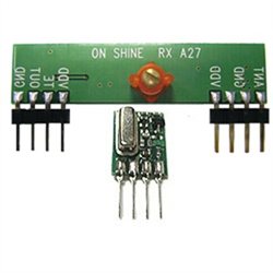

Will this A27 Tx/Rx combo work as an alternative?
I should be getting a couple of 107s in the next week.
This is going to be my first mod when I can get around to it ![]()
Raptor said
Here is a guide i made to do the gyro mod, i hope its of some interest.
Genius! I'm definitely going to have a go at this, thank you ![]()


 Offline
Great info-think better to put this post on Random mods as will be seen more-ok with you?
"Fly like a butterfly sting like a Syma" http://syma107.com
Offline
Good mod-the less the weight the faster they go- have you tried the tail rotor mod? http://syma107.com/syma-s107-m.....fications/ and also Dales battery modification ?
"Fly like a butterfly sting like a Syma" http://syma107.com
I know I'm not the first person to Mod a S107G , but I did and I like the outcome. I would not have thought of it had I not read in this forum about it. My S107g was in stock form until yesterday.
All I did was to remove the Main boom supports and the top horizontal wing the was attached to them. I left the tail fin next to the rear propeller as a safety device to protect the rear prop from damage.
Test flight proved to be a nice change. This little Heli really does fly faster and is waaaay more agile. I couldn't beleive the way this thing fly's now compared to stock. The S107 fly's very nice out of the box, but I like this mod better.
Here's what I found out while doing this mod;
1. I didn't have a phillps screwdriver small enough for the screws, so I used an inexpensive eyeglass repair kit screwdriver, and it worked great.
2. Most all of the screws required tightening up. I've probably flown this thing 70 times.
3. I lubed the plasctic gears with a dry teflon lubricant That I use to lube the actions of some of my guns. It goes on dry and does not pick up dirt, hair, etc. It's called Rem lube.
Now that I have done this Mod I have a few spare parts, so I found a small wooden candy box for storage. Now I keep all the spare screws, Heli parts, screwdriver, small pliers, charge cord, parts manual, and soon a complete blade rebuild kit which should be here soon. The little box is good as a Heli pad while charging.
Anyway I know I'm not the first to make this Mod, and would like to thank all that have done this and posted it, so a anoob like myself could try it out.
Chief T ![]() >
>

Excellent!!! Love mode 6 looks like she is smiling ![]()
![]()
i put the rf mod on the back burner for a little bit but in the mean time here's what i've been working on:

ah, sorry about not replying sooner (i had wrote a reply, but must not have clicked on send)
Sorry to hear that it is not working.
The receiver board has no reverse polarity protection that i can see. If the voltage is connected in reverse, it is highly likely that it will be damaged beyond repair.
I hope that the part arives soon.
thanks for the help raptor
i think i messed this one up tho. i laid out the circuit you provided, but the LED didn't light. I'm still not sure where the problem is tho.
On the rx, i read a voltage between VCC and GND and even between VCC and DATA OUT but the best I could get between DATA OUT and GND was ~0.2v
On my tx, for some reason, there was a voltage between VCC and the RF SIGNAL wire as soon as I turned the controller on, and it would drop ~0.3v at full throttle, but I have a feeling that's wrong. Did i damage the circuits by initially hooking up the transistors backwards? That's about the only thing I can think that I did wrong/deviated from your instructions.
I'll probably order another circuit and try this again soon after I figure out where I went wrong

Hopefully this quick sketch shows how a quick test setup.
as there seems to be some problems with the setup, as a last resort i think the modules need to be tested.
The way i did this on mine, was to connect the transmitter module to a 5v battery, and and attach an antenna. with a on/off switch between the signal and Live connections.
On the receiver, i connected a lipo battery, an antenna, and a LED between the signal and ground.
when you switch on and off the transmitters signal, the LED should turn on and off, as you press the button. (if you don't press it/hold it down than it will start flickering after about 1second, but this is normal)
The circuit within the transmitter, decodes the the IR pules, and removes the 38khz modulation, into a frequency that the RF modules can handle. The transistor inverts the signal as the IR receiver is normally high (which the RF module doesn't like).
The transistor on the helicopter inverts the signal again so that the helicopter can recognize the signal.

i thought i found the solution, yet i'm still stuck.
looking at the datasheets for the 2n3904 and 2n3906, i realized the collectors and emitters are opposite those of the bc547 and bc557. so i flipped both the transistor in the rx and tx but its still not working.
when giving throttle, should there be a voltage between the RF signal wire and GND in the tx? i checked with my multimeter and everything is getting power until i get to the RF signal wire, it only reads ~.2v.
i also went back and re-soldered the antenna wire as well as
Does this work by using the IR LED to read the signal from the remote and translate it to RF before sending it to the rx module?
before you go any further. On the first image that you sent me.there looks to be a bit too much of the antenna sticking through.
Try cutting off the excess antenna wire on the back of the receiver circuit. It may let it pick up a signal.
yeah i'll replace the transistor side of the circuit later and let you know how it goes...i had a bit of trouble removing a pin but it was the pin between the antenna and gnd pins so its not even in use and the board is getting power and sending the power over the the vcc and gnd pins on the other side...the LED doesn't light up and my voltage meter only read about .1v between OUT and GND
sorry, i meant to say its the receiver circuit attached to the helicopter that seems to be having the issue, not the S107 helicopter itself.
this issue could be caused by numerous different issues.
i.e antenna shorted to ground, no power going to the receiver circuit, resistors being damaged, transistor damaged by too much heat, etc.
the LED doesn't light up when i connect it to the rx module so i'll take a look into that
i dont think its the helicopter...i did this mod to a stock one, the only other mod being the diode bypass for power
I meant, using a spare LED, hold it onto the helicopters circuit to see if it was receiving a signal.
Hold the long leg (positive) on the "OUT" part of the circuit, and the short (negatve) leg to "GND"
it should light up in the same pattern as the one on the transmitter.
from what you have said so far, it sound like the issue is on the helicopter.
i've checked the tx with a voltage meter and everything seems to be getting power
the red LED on helicopter, is that between the middle resistor and the leg without one?
Sorry about the confusion over the capacitor. I made a silly mistake...
It should read 0.1uF (104 ceramic capacitor) however any electrolytic capacitor should work too, as long as the negative pin is pointing towards the bottom of the circuit.
After looking at the images you sent me, i cant see anything that is obviously wrong with your circuit.
I noticed that you used a Tantalum capacitor, did you put it in in the correct polarity.
also try placing a RED led between the signal wire on the helicopter and ground, it should give a visual indication if it is working.
edit: the size doesn't really matter, it smooths out the spikes in the supply. If the test LED and the IR LED's are blinking in synk, like you said, then it shouldn't be a problem.
p.s. do you have a voltage tester? if so check that there is at least 3v between the VDD and ground pins.
Also check that the antenna wire is not shorted/touching the ground plate of the circuit.
Most Users Ever Online: 211
Currently Online:
7 Guest(s)
Currently Browsing this Page:
1 Guest(s)
Top Posters:
MikeK: 178
SymaGuru: 32
justdon: 9
nope: 5
smith: 2
groggy: 2
Member Stats:
Guest Posters: 729
Members: 20
Moderators: 0
Admins: 2
Forum Stats:
Groups: 7
Forums: 16
Topics: 1283
Posts: 8215
Newest Members:
Administrators: Syma Freak: 1452, JamDJ: 264
